The MRI System#
Every MRI system consists of several major components, required to create measureable magnetic resonance phenoma and to perform spatial localization. This section will deconstruct a MRI scanner and see what is inside. This will give insight into the fundamentals of a MRI experiment and what is hardware is required.
Learning Goals#
Describe the 4 fundamental components of a MRI scan and why they are necessary
What are the required components of MRI system?
What is the purpose of these components?
What calibrations are required for a MRI scan?
Answer these questions:
Why is MRI so loud?
Why is it dangerous to bring certain metals into a MRI scanner?
Components of a MRI Scanner#
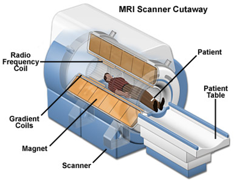
If we cut open a typical MRI scanner, it would look like this

The scanner consists of 3 hardware components that are required for all MRI scans
Main magnet - \(B_0\)
Radiofrequency (RF) coils, including a transmit RF coil - \(B_1^+(\vec{r},t)\) - and a receive RF coil - \(B_1^-(\vec{r},t)\)
Magnetic field gradient coils - \(\vec{G}(t)\)
Main magnet - \(B_0\)#
The purpose of the main magnetic field is “Polarization”. This refers to the preferential alignment of nuclear spins with a magnetic field. The more alignment there is of spins, the greater the MRI signal. The stronger the magnetic field, the more alignment and therefore the stronger signal that will be received.
This magnetic field is typically 1.5 Tesla (1.5 T) or 3 T. It is designed to be homogeneous. To achieve this large of a mangetic field typically requires using a superconducting magnet, which consists of a superconducting alloy bathed in liquid helium, and this type of magnet is always on.
Due to \(B_0\), there is a large magnetic field inside and around the MRI scanner, making it very dagerous to bring certain materials near the scanner. These materials, typically metals that are ferromagnetic like iron, can be sucked into the scanner by the powerful magnetic field.
Radiofrequency (RF) coils - \(B_1^+(\vec{r},t), B_1^-(\vec{r},t)\)#
The purpose of the RF coils is “Excitation” and “Acquisition”. RF coils are antennas designed to detect changes in electromagnetic fields in the radiofrequency range. These coils and associated components must be tuned to the resonance frequency for the MRI system in order effectively transmit and receive signals at the resonance frequency.
Excitation refers to depositing energy at a specific frequency that perturbs the spins, causing them to resonate and release energy that is captured as the MRI signal. This is performed using a transmit RF coil, described by the magnetic field \(B_1^+(\vec{r},t)\). This energy is deposited in the radio-frequency (RF) range, typically in the 100 MHz range for MRI, which is the resonance frequency.
After Excitaiton, the spins release energy, also in the RF range, as they return to thermal equilibrium. This is measured in Acquisition where the signal is detected by the receive RF coil, described by the magnetic field \(B_1^-(\vec{r},t)\).
The RF coils are typically separated into separate transmit and receive coils because of different requirements: the transmit coils for excitation are designed to be homogeneous in depositing energy across the field-of-view (FOV), while receive coils are designed for maximum maximum sensitivity to the relatively small signals detectable from the spins.
Magnetic field gradient coils - \(\vec{G}(t)\)#
The purpose of the magnetic field gradient coils is for “Spatial Encoding”, which enables creation of images. These coils, commonly refered to simply as “gradients”, are designed to create linearly varying magnetic fields. These varying magnetic fields add and subtract from the main magnetic field. Since the magnetic field determines the resonance frequency (\(f = \bar{\gamma} \|\vec{B}\|\)), this will create a spatial variations in the magnetic field that can be used to separate signals from different locations and ultimately create images.
The noises during a MRI scan are due to the rapid switching of electric currents in the gradient coils. The change in electric currents and resulting change in magnetic field interacts with the main magnetic field and exerts a force (known as Lorentz force) on the gradient coil. Thus the gradient coils will vibrate as they are switched on and off, creating loud noises.
Fundamental MRI Experiment Procedure#
Polarization: Place subject in a large magnetic fiel
Components required: main magnet, \(B_0\)
Excitation: Perturb the spins from equilibrium by applying RF energy
Components required: transmit RF coil, \(B_1^+(\vec{r},t)\)
Acquisition: Detect the changing magnetic field RF energy from excited spins
Components required: receive RF coil, \(B_1^-(\vec{r},t)\)
Spatial Encoding: Create spatial variations in the magnetic field to distinguish spins at different locations. This can occur during excitation and acquisition.
Components required: Magnetic field gradient coils, \(\vec{G}(t)\)
Repeat Excitation, acquisition, and encoding as needed to acquire enough data to form an image

Calibrations#
Calibrations are performed of the individual components of a MRI scanner both when the system is installed and during each scan.
Installation Calibrations#
Main magnet: Minor adjustments to the main magnetic field, called “shimming”, is performed to make the main magnetic field more homogeneous
RF systems: Checking for sources of RF interference entering the scanner room
Gradient coils: Calibration of the gradient strength and mapping of the gradient fields to ensure accurate spatial encoding.
Pre-scan Calibrations#
Different people and different places in the body will create differences in both the main magnetic field as well as the RF fields due to loading and magnetic susceptibility, thus requiring calibrations to be performed for each scan. This is sometimes referred to as “prescan”.
Main magnetic field: Measurements of the resonance frequency across the imaging field-of-view are used to perform shimming and choosing the correct RF frequency (“center frequency”)
RF systems: The transmit RF field created, \(B_1^{+}\), is calibrated by modifying the RF transmit power, implemented via amplifier gains. Often, the RF receive coil profiles, \(B_1^{-}\), are also measured for intensity correction and accelerated imaging methods.
